User Coordinate System (UCS)
- Lesson 3-1INTRODUCTION TO 3-D (Terminology)
- Lesson 3-2ISOMETRIC DRAWING IN AUTOCAD
- Lesson 3-3WORKING IN 3 DIMENSIONS (X,Y,Z Axes, 3D Rotation)
- Lesson 3-4VIEWING 3-D OBJECTS (Perspective Views, 3D Orbit, DView)
- Lesson 3-5BASIC WIREFRAME MODELS
- Lesson 3-6LINE THICKNESS
- Lesson 3-7REGIONS AND 3-D FACES AND EXTRUDING
- Lesson 3-7aMORE ABOUT EXTRUDING & LOFTING
- Lesson 3-8REVOLVED OBJECTS - REVSURF AND REVOLVE
- Lesson 3-9ADDING MATERIALS IN AUTOCAD
- Lesson 3-10PRIMITIVE SOLIDS
- Lesson 3-11BOOLEAN OPERATIONS AND 3D EDITING
- Lesson 3-12CHANGING FROM THE WCS TO THE UCS
- Lesson 3-13MAPPING MATERIALS
- Lesson 3-14CREATING NEW MATERIALS
- Lesson 3-15EXTRA PROJECTS AND A TUTORIAL
- Lesson 3-16PUTTING IT ALL TOGETHER - MODEL A BUILDING
- Lesson 3-17INTRODUCTION TO RENDERING AND LIGHTING IN AUTOCAD
- Lesson 3-18CREATING ANIMATIONS IN AUTOCAD
- QUIZ FOR LEVEL 3 - 84 QUESTIONS
Topics covered in this Lesson:
Setting and Using the UCS | Dynamic UCS
When working in 3D, it sometimes necessary to change the plane that you are drawing on. For example, if you need to add some detail to the side of a wall, you would want to draw on that plane. It's like taking a sheet of paper up off the floor (WCS) and taping it onto the wall (UCS).
The WCS is the World Co-ordinate System. This is the way that the default X,Y and Z axes are directed when you begin a new drawing (X to the right, Y pointing up and Z pointing towards you). The UCS is the User Co-ordinate System. This is a ‘redirection' of the WCS based on parameters set by the AutoCAD user.
There are several ways of doing this, and we'll look at an example here.

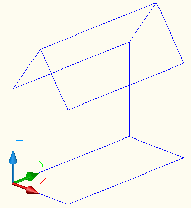
This is a simple shape drawn on the WCS with one corner located at 0,0,0.
Here is the same object shown a new UCS based on the side of the object, so that you are able to draw on the side of the building - maybe to put a door in? Note the direction that the X and Y axes are now pointing.

Notice that the positive X Axis is now pointing along side of the structure.
Here's how it was changed:
First start the UCS command. You first choose the 3 point option by typing 3 at the prompt. Next you have to pick three points to define the plane. The first point is the new origin. The second point is where you want the positive X-axis to be positioned. The last point is for the positive Y-Axis.
Command: UCS
Current ucs name: *NO NAME*
Enter an option [New/Move/orthoGraphic/Prev/Restore/Save/Del/Apply/?/World]
<World>: 3
Specify new origin point <0,0,0>: <P1>
Specify point on positive portion of X-axis <1.0000,7.0000,0.0000>: <P2>
Specify point on positive-Y portion of the UCS XY plane
<1.0000,7.0000,0.0000>: <P3>

This is the ‘3-Point' option of the UCS Command. It is one of the most useful, because you control exactly where the new drawing plane will be. You must also be extremely careful when picking the 3 points, or your plane can be shifted and cause some major problems. I would recommend using this method for most of your UCS work - or at least get very comfortable with it before moving on to other methods. Make sure you are using Osnaps to select your points accurately.
NOTE: Pressing enter immediately after entering the UCS command accepts the default of returning to the WCS.
Here are examples of the other options of the UCS command.
ORIGIN: This option moves the UCS based on a newly picked origin point. It does not shift the drawing plane at all as you only pick one point.
ORIGIN:
Command: UCS
Origin/ZAxis/3point/OBject/View/X/Y/Z/
Prev/Restore/Save/Del/?/<World>: O
Origin point <0,0,0>: <PICK A POINT>
Z-AXIS: This choice allows you to pick two points to define the direction of the Z-axis. First you pick the new origin, then you pick a point for the positive Z-Axis.
Command: UCS
Origin/ZAxis/3point/OBject/View/X/Y/Z/
Prev/Restore/Save/Del/?/<World>: ZA
Origin point <0,0,0>: <PICK A POINT>
Point on positive portion of Z-axis <-8.0000,0.0000,1.0000>: <PICK A POINT>
OBJECT: Using this method, you have to pick on a 2D object that is lying on a particular drawing plane. This gets tricky, as you have to be aware how your positive X and Y axes end up. You also need to know how the object was drawn originally as this defines its plane.
Command: UCS
Origin/ZAxis/3point/OBject/View/X/Y/Z/Prev/Restore/
Save/Del/?/<World>: OB
Select object to align UCS: <SELECT AN OBJECT>
VIEW: By choosing the view option, AutoCAD will automatically reset the UCS to be aligned with your current view, keeping the origin where it was previously located.
Command: UCS
Origin/ZAxis/3point/OBject/View/X/Y/Z/Prev/Restore/
Save/Del/?/<World>: V
X / Y / Z: By selecting either the X, Y or Z options, you need to first pick a point along the axis you have chosen, then provide a rotation angle based on the right hand rule mentioned earlier. This example shows how you would rotate the UCS -90 around the positive X axis.
Command: UCS
Origin/ZAxis/3point/OBject/View/X/Y/Z/Prev/Restore/
Save/Del/?/<World>: X
Rotation angle about X axis <0>: -90
PREVIOUS: This option returns you to the last setting you had for the UCS. You'll use this one a lot in 3D. You might need to change your UCS to draw one object, then go back to what you had it set at before.
Command: UCS
Origin/ZAxis/3point/OBject/View/X/Y/Z/Prev/Restore/
Save/Del/?/<World>: P
Restore/Save/Del/?/: The next options are used in conjunction with each other. You have the option of saving a particular UCS with a name. You can then restore that named UCS or delete if you no longer will be using it. Here are examples of these options:
Command:UCS
Origin/ZAxis/3point/OBject/View/X/Y/Z/Prev/Restore/
Save/Del/?/<World>: S (Save a UCS Setting)
?/Desired UCS name: VIEW1Command:UCS
Origin/ZAxis/3point/OBject/View/X/Y/Z/Prev/Restore/
Save/Del/?/<World>: R (Restore a UCS setting)
?/Name of UCS to restore: VIEW1Command: UCS
Origin/ZAxis/3point/OBject/View/X/Y/Z/Prev/Restore/
Save/Del/?/<World>: ? (List your UCS settings)
UCS name(s) to list <*>:
Current UCS: VIEW1
Saved coordinate systems:
VIEW1
Origin = <0.0000,0.0000,0.0000>, X Axis = <1.0000,0.0000,0.0000>
Y Axis = <0.0000,1.0000,0.0000>, Z Axis = <0.0000,0.0000,1.0000>
Origin/ZAxis/3point/OBject/View/X/Y/Z/Prev/Restore/
Save/Del/?/<World>: D
UCS name(s) to delete <none>: VIEW1
Deleted 1 UCS name.
This was a series where a view named VIEW1 was saved, restored, listed, and then deleted.
DYNAMIC UCS
Another option to try is using Dynamic UCS, but I
don't recommend this technique for new users. Here it is anyway. Down on the status bar, you
have an icon that turns this setting on or off. You can also toggle this on and off
with the F6 key.
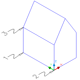
With Dynamic UCS turned on, you can easily draw on any surface you want. If you have a drawing like the basic building shown at the top of the page, you can draw a rectangle or box on the roof without manually setting a new UCS. The key is to look and see which face is highlighted as you move your cursor on the screen.
In the images below, you can see how this works. The left side shows the 'roof' face is highlighted and the cursor has changed to reflect the new UCS. The right shows how this looks when the right side face is active. Not the change in the colored cursor while the UCS Icon remains the same.

Other notes about the UCS:
Be careful when choosing a UCS. Look to the UCS icon and see that it is aligned the way you want it to be. Look for a clean vertical lines if it should be aligned along a vertical plane. Most of the time I will use the 3 Point UCS option and then Previous to return and then back to a different 3 point option and so on. 3 Point gives me a lot of versatility without having to think about it too much (and concentrate on how I'm going to draw the project.
Always be aware of where your UCS is located. Make sure that positive X is where you expect it to be.
Extra Practice: Create this drawing by switching the UCS to the correct plane to draw the roof and skylights. For the geometry, use a combination of extruding and boolean operations to build it.
Extra Practice: Create this drawing by setting the UCS to achieve what you need. Tip: Extrude a rectangle, set the UCS and extrude another rectangle.
Video: Setting the UCS / Dynamic UCS
You Scored:

Fun fact: In 1974-1975 John Walker, one of the founders of Autodesk, wrote the ANIMAL software, which self-replicated on UNIVAC 1100 machines. It is considered one of the first computer viruses.
Please support
MyCADsite.com
Give a donation!
Donate

- To cover this months server costs
- Exceeding amounts will go to creating new content
- Even a penny will help
Did you like the lesson? ❤️
